Mechanical Engineering Lab Reports

Thursday, December 10, 2009

Thermocouples

Objectives

- To describe how the thermocouple functions.
- To describe the use o a thermocouple with a Wheatstone bridge circuit for the measurement of temperature.
- To know the different types of thermocouples.
- To calculate the rise time of a thermocouple.

Introduction:

The measurement of temperature in industrial processing is an important concern. Temperature is the most important effect on certain manufacturing processes as well as on the physical manufacturing environment. Without information about the temperature of materials & its environment, manufacturing technology would be crude by today's standards. Temperature transducers are utilized to convert temperature changes into electrical changes. The electrical variations can be displayed on a meter or recorder. The thermal transducers most often employed are the thermocouples, thermistors & RTD.
Apparatus:

- Master builder S300B.
- Insertion panel SIP380-1.
- Digital multimeter.
- Hand made type J (iron-constantan) thermocouple wire & commercial type J thermocouple wire.
- Electric solder.
- Stop watch.
- Connection leads.


Review & discussion:

- What is a thermocouple?

It is a thermal transducer or thermal sensor that converts temperature changes into electrical changes; it is formed by a junction of two dissimilar metals, such as iron & constantan (type-J) or chromel & tophel (type-K). The junction when heated it produces a small voltage & associated current flow, the voltage developed is directly proportional to the junction's temp.

- What determines the amplitude of change at the output of a thermocouple amplifier?

The type of the materials used in making a thermocouple & the supplied temperature.

- Refer to figures 11-9 & 11-10 in the manual. Which thermopile would produce the largest voltage deflection?

The thermopile in fig. 11-10 because the thermocouples are connected in series which causes a larger voltage difference than the connection in fig. 11-9.

- What are thermopiles?

Thermopiles are series & parallel groups of thermocouples that can be used to increase both the voltage & current outputs of a group of thermocouples.

- Explain the term "time constant"

Time constant (τ) is the time needed to reach 63.8% of the final value in a transient response device.

- What metals are used to construct a J-type thermocouple & K-type?

J-type: Iron-Constantan.
K-type: Chromel tophel-Alumel.

- Refer to figure 11-4 in the manual. Name a type of thermocouple which could be used to 4000o F.

According to the figure we can see that a (C-type) thermocouple can be used to 4000o F.

- Which metal is the positive element of a J-type & K-type thermocouple? (Use fig. 11-6 in the manual).

J-type: Iron.
K-type: Chromel.

- What type of thermocouple can be used to 2300o F & would yield a high output voltage?

According to figure 11-4 in the manual the answer is (K-type) thermocouple.

Sin Bar and Angular Measurements

Objectives

To get familiar with the use of bevel protractor, vernier protractor & clinometer for measuring angles.

Apparatus

  • Plain bevel protractor.
  • Vernier protractor
  • Clinometer
  • A metallic triangular specimen


Plain bevel protractor:

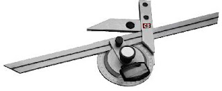
When two surfaces are at any angle other than 90o, the angle between them must be tested with some form of protractor. Instruments for this purpose may have a scale of degrees, enabling the angle to be read off, or they may consist of gauge which must be set to the angle before use. And the bevel protractor in fig. 1 is an example of this second variety of gauges, & must be set to the correct angle before use.

Plain bevel protractor

Vernier Protractor:

The main scale of this device is divided up into degrees from 0o to 90o each way. The vernier scale is divided up to that 12 of its division occupying the same space as 23o on the main scale, thus 1 vernier division = 23/12 = 1.92 degree on main scale. The instrument therefore allows settings to 5 min of angle to be obtained, so we use it to get accurate readings. This device has a movable arm, plate blade, fixed nut & vernier scale, see fig. 2.

Vernier Protractor

The Clinometer:

The clinometer is a special case of the application of the spirit level. In this instance the level is mounted in a ratable body carried in a housing, one face of which forms the base of the instrument. A main use of the instrument is the measurement of the included angle of two adjacent faces of a work piece. Thus, in use, the instrument base is placed on one face and the rotating table body is adjusted until a zero reading of the bubble is obtained. The angle of rotation necessary to bring this about is then shown on an angular scale moving against an index.

A second reading is taken in a similar manner in the second face of the work piece, the included angle between the faces being the difference the first & the second readings. Depending upon the type of instrument used, readings direct to 1 min are obtained, & up to a range of movement of 90o, see fig. 3.

Main scale = 360o.

Vernier scale: Full revolution = 1o = 60 min, so each division on vernier scale = 1 min.

The clinometer

Procedure

First of all we clean the component & remove the burrs if there are any, also make sure that the surface plate is nice & clean. In order to avoid compound angle error care must be taken in aligning the work piece with the measuring tool.

Then we take the readings of angles 1, 2 & 3 on the specimen using each of the provided equipment then fill the results in table 1.


Discussion

The personal skills needed for taking angular measurements are to know exactly how to fit the desired angle on the specimen on the measuring device & holding it still, an additional skill is needed when using the vernier protractor which is to know how to take the reading precisely.

The overall time needed to take the readings depends on the personal skills of the one taking the reading.